
Geo-Redundant Multi-Cloud Interconnect using FCR and IP-WAN aligned with Azure Maximum Resiliency ER and GCP 99.99% Partner Interconnect
1. Summary
This document presents a validated, geo-redundant multi-cloud architecture for Microsoft Azure and Google Cloud, built using Equinix Fabric Cloud Routers (FCRs) and IP-WAN. It serves as both a technical reference and a deployable guide; covering architecture design, step-by-step deployment, and validated failure scenarios. The primary intent is to deliver a fully redundant multi-cloud interconnect with no single point of failure, and to document the observed traffic behaviour under default routing conditions. Convergence time measurement, is outside the scope of this validation. The focus is on routing correctness: confirming that the expected failover paths are activated and that reachability is maintained.
1.1 Solution Overview
The design leverages Equinix FCRs and IP-WAN to deliver a geo-redundant, multi-cloud network architecture located in two distinct Equinix metros. The solution is aligned with official Microsoft Azure and Google Cloud resiliency guidance, meeting Azure Maximum Resiliency option via ExpressRoute (ER) and GCP's 99.99% availability SLA option via Partner Interconnect, providing resilient interconnects from distinct on-ramp locations. This eliminates single points of failure across Equinix and cloud provider infrastructure, every component and connection is redundant across diverse paths, delivering the highest level of resilience for business-critical and mission-critical workloads.
Representative failure scenarios, ranging from single connection loss to metro‑level isolation, have been tested and validated, confirming that the expected failover paths are activated and reachability is maintained as designed.
While this design focuses on the multi‑cloud interconnect use case, the same FCR construct can be extended to integrate physical colocation, on‑prem environments, and other Equinix services; these extensions are intentionally out of scope for this document.
Beyond resiliency, FCR brings clear advantages to the solution: high performance connectivity, low latency, and edge deployment without licensing overhead, ready to deploy in minutes.
1.2 High-Level Architecture Diagram
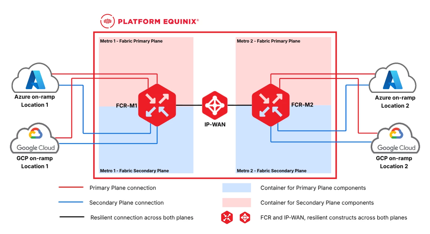
Key Outcomes
- This design delivers: Equinix FCR and IP-WAN architecture spanning two distinct metros
- Alignment with Microsoft Azure ExpressRoute Maximum Resiliency
- Alignment with Google Cloud Partner Interconnect 99.99% SLA Option
- Steady-state traffic flow analysis across both cloud providers
- Failure scenario validation for resiliency proving; from single connection loss to complete metro isolation
- Step-by-step deployment with configuration parameters for Equinix and for relevant Azure/GCP interconnection services.
2. Technology Stack & Scope
List only the technologies intentionally used in this design. Be explicit about what is out of scope to avoid ambiguity.
2.1 Technology Stack
| Category | Components |
|---|---|
| Equinix Services |
|
| Cloud Providers private interconnection services |
|
2.2 Out-of-Scope
| Item | Explanation |
|---|---|
| CSP Network details | This EVD does not cover Cloud Provider network design decisions in detail. Only the configurations described by their respective resiliency guides (Azure Maximum Resiliency and GCP 99.99% Partner Interconnect) are followed. |
| BGP Traffic Engineering | No BGP attribute manipulation or traffic engineering is applied on any device. All traffic path observations reflect default path selection behavior. |
2.3 Supplementary Components Used in This EVD
The following components and parameters were used for validation purposes only. In a production deployment, customers should select specifications that align with their configurations, performance, capacity, and contractual requirements.
| Component/Parameter | Specification |
|---|---|
| Equinix Fabric Virtual Connection speed | 50 Mbps (it is sufficient for functional and resiliency validation; performance stress testing is not in scope) |
| FCR Package | FCR Basic package (it is sufficient, route scaling stress testing is not in scope) |
| FCR Contract Term | on-demand (select the term that fits your needs; longer commitments offer additional discounts) |
| FCR instance names | FCR-FR (Frankfurt) FCR-PA (Paris) |
| Equinix metro locations and respective Cloud on-ramp locations | Frankfurt (FR) Paris (PA) |
| IP-WAN Network Type | Regional (both metros are within EMEA) |
| Tester Devices for ping and traceroute | 2x Network Edge (Cisco 8000v) devices in Equinix Platform, each connected to respective FCR 2x VMs in Azure Germany West Central and France Central regions 2x VMs in Google Cloud europe-west3 and europe-west9 regions |
| Azure regions | Germany West Central (Frankfurt) France Central (Paris) |
| Azure ExpressRoute SKU | Standard |
| Azure ExpressRoute circuit names | evd_fr_er (Frankfurt) evd_pa_er (Paris) |
| Azure VC names | &fcr-fr-to-ergw-fr-pri / sec fcr-pa-to-ergw-pa-pri / sec |
| GCP regions | europe-west3 (Frankfurt) europe-west9 (Paris) |
| GCP VC names | fr-vc-pri / sec pa-vc-pri / sec |
3. Low Level Design
This section presents the technical specifics of the solution: how it is designed, how components connect, route, and operate, what assumptions were made, and what design decisions were taken to achieve the intended outcome.
3.1 Prerequisites
Review and confirm the following prerequisites for each platform before proceeding with the deployment.
- Equinix prerequisites:
- Create or ensure an active Equinix account following the New Customer Onboarding guide.
- Create or ensure user(s) with the appropriate access rights. For this design, Fabric Manager and Fabric Cloud Router Manager roles are sufficient. Refer to the Identity and Access Management documentation , specifically the "Inviting New User" and "Managing Users' Roles" sections.
- Create or ensure Billing Account(s) covering both metros per the Creating Billing Account guide. A Global Billing Account is recommended for digital services and operational simplicity.
- Cloud prerequisites:
- Active Azure account with an active subscription per following Create and modify ExpressRoute circuits prerequisites guide.
- Establish your Google Cloud organization, administrators, and per their Guided Flows.
3.2 Logical & Physical Design
This section covers the key design considerations for location selection, cloud provider requirements, and Equinix platform configuration options. Refer to Appendix 6.1 for the complete IP address plan.
3.2.1 Location selection
Evaluate and select the Equinix metro, cloud region, and peering location before finalizing the architecture.
- Equinix Location Selection:
- FCR is metro-scoped: A Fabric Cloud Router (FCR) instance is deployed per Equinix metro (not globally); therefore deploy one FCR per metro used in the design.
- Equinix metro concept: An Equinix metro represents a group of data centers in proximity, interconnected with low-latency (sub-millisecond) links. A metro is a concept similar to a cloud region, so it is recommended to align Equinix metros with cloud providers regions where possible.
- Azure Location Selection:
- Metro alignment for cloud on-ramps: Because FCR is metro-scoped, select an ExpressRoute peering location in the same metro as the FCR that terminates the connection. Refer to Azure’s ExpressRoute connectivity partners and peering locations guide to confirm availability.
- Region vs peering location: The Azure resource region (where VNETs/workloads live) does not have to match the ExpressRoute peering location. However, ensure the chosen ExpressRoute SKU scope supports the intended connectivity and review data egress cost implications (especially if using Metered).
- Design choice: For this validated design, we selected the same Azure region as the peering metro to optimize operational simplicity, latency, and cost.
- GCP Location Selection:
- Metro alignment for Partner Interconnect: Because FCR is metro-scoped, select the Partner Interconnect location in the same metro as the FCR used for that interconnect termination. Refer to Google Cloud’s Supported service providers guide to confirm availability.
- Interconnect location vs. region: Partner Interconnect location is independent of the GCP region where workloads run. For this design, we still prefer aligning GCP region, Azure region, and Equinix metro to reduce latency and simplify operations.
- Egress pricing consideration: Cloud Interconnect egress discounting depends on the VLAN attachment region; when workloads are in a different region than the VLAN attachment, cross-region charges may apply.
- Design choice: For this validated design, we selected the same GCP region as the interconnect metro to optimize performance and cost predictability.
3.2.2 Provider design considerations
This section summarizes the Equinix Platform configuration choices and cloud provider design requirements that influenced the validated architecture. The diagrams that follow illustrate how the provider constructs, FCRs, IP-WAN, and redundant virtual connections are combined to meet the target resiliency model.
Equinix Platform design considerations:
- Select FCR Package: Use the FCR Service Packages reference to compare features and choose the package that matches your virtual connection speed and route scale requirements. Packages are upgradeable, so starting with a smaller tier and scaling later is a supported path.
- Select FCR Metro: Deploy an FCR in each Equinix metro where routing capability is required, because FCR instance is metro-scoped. Each FCR is highly available within a metro (covering both redundancy planes), so resiliency is achieved through redundant connections rather than redundant routers. Note that each metro assigns a fixed ASN to its FCRs; this value cannot be changed and is visible during creation and in the FCR overview.
- FCR prioritizes routes learned from local VCs over those received via the IP-WAN connection.
- Select IP‑WAN Network Type (Regional/Global): FCR-to-FCR connectivity across metros requires an IP-WAN; a multipoint construct that enables two or more FCRs to exchange IP prefixes. Select the appropriate Network Type (Regional or Global) based on whether the connected metros are within the same geographic Equinix region or span multiple regions. Note that, this choice directly impacts pricing as well. Use IP-WAN Network Types as a guide.
- Select metros with Azure and GCP availability: Ensure the selected metros support the desired cloud on‑ramps via Equinix Fabric (Azure ExpressRoute and GCP Partner Interconnect availability varies by location). Use the Cloud Provider pages in Equinix Website and the provider pages (Google Cloud and Microsoft Azure) to confirm availability before finalizing the metro selection.
Microsoft Azure design considerations:
- Follow and apply the virtual network topology, gateway redundancy, cross-site connectivity, and BGP routing design requirements described in Maximum Resiliency and Large distributed enterprise network guides. These define the baseline ExpressRoute architecture this design builds upon.
Google Cloud design considerations:
- Follow and apply the VLAN attachment, Cloud Router, prefix advertisement, and VPC requirements described in Establish 99.99% availability for Partner Interconnect guide. This defines the Partner Interconnect redundancy model this design follows.
Platform-Specific BGP dependencies: They don't affect the overall EVD, but you should be aware of them during implementation.
- FCR ASN is fixed per metro and cannot be changed.
- Azure ExpressRoute private peering ASN is fixed at 12076, cannot be changed.
- GCP Cloud Router ASN is fixed at 16550 for Partner Interconnect.
- GCP Partner Interconnect uses link-local addresses (169.254.0.0/16) assigned by GCP; customer cannot choose the IP addressing for FCR-to-GCP peering links.
- When you consider faster failure detection, BFD minimum intervals are constrained by each provider’s portal limits. The table below summarizes the supported boundaries and the values configured in this EVD:
| Provider | Min BFD Interval | Configured in EVD |
|---|---|---|
| Equinix | 100 ms | 300 ms (Azure) 1000 ms (GCP) |
| Azure MSEE | 300 ms (fixed) | 300 ms |
| GCP | 1000 ms | 1000 ms |
Traffic Engineering:
- This design does not implement any traffic engineering. All traffic paths follow default BGP path selection without attribute manipulation (such as local preference, AS-PATH prepending, or MED).
Test devices:
- NE Testing Devices: Two Network Edge devices, one per metro, are directly peered with the local FCR. They represent on-prem routers and are used to validate reachability and path selection using ping and traceroute, and to inspect routing information (e.g., learned and advertised prefixes) during normal operation and failover testing.
- VMs in Cloud Provider: Two VMs per CSP, one per region, for a total of four. These VMs serve purely as test endpoints for reachability and path validation. Availability-zone-level redundancy for these VMs is not in scope for this EVD.
Resiliency and Routing Diagrams:
This design delivers a geo-redundant, multi-cloud architecture spanning two distinct Equinix metros. Every component in the path; FCRs, IP-WAN, Cloud Router, VNET Gateways are natively redundant, and connections are doubled across diverse planes, eliminating single points of failure across the entire topology. Additional interconnection resiliency is achieved through diverse on-ramp locations in separate metros, fully aligned with Azure Maximum Resiliency for ExpressRoute and GCP's 99.99% availability SLA for Partner Interconnect.
Failure scenarios confirming this resiliency model are documented in Section 5.


- BGP peering between FCRs over the IP-WAN backbone is established automatically; no customer configuration is required.
- Azure ExpressRoute Gateways can connect to ER circuits across different peering locations, learning subnets and exchanging routes via BGP for redundancy. By connecting gateways in each region to both local and remote circuits, cross-region failover is achieved; if the local circuit fails, traffic reaches Azure via the remote circuit over the Microsoft backbone. For VNet-to-VNet communication, Azure recommends VNet peering rather than routing through ExpressRoute.
- GCP Cloud Routers attach directly to each VLAN attachment in the same location, exchanging all VPC routes using global dynamic routing mode for cross-region reachability.
3.2.3 Steady-state Traffic Paths and Diagrams
The following diagrams show the expected traffic paths under normal operating conditions, with all links active and no failure or traffic engineering applied.
This design does not apply traffic engineering or BGP attribute manipulation. Alternative routing configurations are outside the scope of this document. The following traffic path diagrams illustrate the observed routing behavior under default configuration.
Traffic path between GCP and on-prem: Illustrated below in Diagram 4 and Diagram 5.
- In global dynamic routing mode, GCP Cloud Router advertises local subnet routes with higher priority than remote subnet routes (Local dynamic routes suppress candidate peering dynamic routes). This means traffic from a GCP VM prefers to egress via the VLAN attachments in its own region, and only uses remote region attachments when local paths are unavailable. Described in the Dynamic route control plane processing section.
- FCR prefers local connections over the ones through IP-WAN.
- Redundant FCR‑to‑GCP connections use ECMP by default, so traffic is distributed across the primary and secondary GCP virtual connections. In other words, the “single path” in the diagram actually represents load sharing across both VCs.


Traffic path between Azure and on-prem:
- With cross-site connections enabled (as required by Maximum Resiliency), each ER gateway has visibility to all four ExpressRoute circuits, both local and remote. Microsoft prefers to route traffic over its own backbone (ER Standard SKU routes traffic through the Microsoft backbone within the same geopolitical region) to reach a remote peering location rather than handing it off locally.
- Azure's route preference pattern combined with FCR's local VC preference results in symmetric traffic path, following the same path in both directions.
- Redundant FCR‑to‑Azure connections use ECMP by default, so traffic is distributed across the primary and secondary ExpressRoute virtual connections. In other words, the “single path” in the diagram actually represents load sharing across both VCs.

Traffic path between Cloud Providers (from GCP to Azure):
- As mentioned previously, GCP VM prefers to egress via the VLAN attachments in its own region.
- Redundant FCR‑to‑CSP connections use ECMP by default, so traffic is distributed across the primary and secondary CSP virtual connections. In other words, the “single path” in the diagram actually represents load sharing across both VCs.

Traffic path between Cloud Providers (from Azure to GCP):
- Azure ER has an interesting route-balancing behavior, it uses ECMP to load-balance outgoing traffic across 4 ER VCs, when advertised routes are identical over all the ExpressRoute paths. This routing behavior is explained here, and the reason behind this is the inter-site connections between ER circuits and ER Gateways, which makes BGP path preference identical across 4 VCs.
- Redundant FCR‑to‑CSP connections use ECMP by default, so traffic is distributed across the primary and secondary CSP virtual connections. In other words, the “single path” in the diagram actually represents load sharing across both VCs.

3.3 Assumptions, Constraints & Dependencies
3.3.1 Assumptions
- Azure ExpressRoute and GCP Partner Interconnect services are assumed to be available in the selected Equinix metros.
- No traffic engineering or BGP attribute manipulation is applied; all routing follows default path selection. Latency- or jitter-sensitive applications may require additional BGP policy tuning beyond this baseline.
- Cloud provider routing behavior remains default as documented at the time of validation. Azure keeps traffic on its own backbone until handing it off at the destination, while GCP Standard Tier exits traffic at the nearest point to the source.
- Cloud-side configuration is limited to network connectivity components (gateways, routers, VLAN attachments, VNET peering). Application configurations, workload deployments and cloud-native security configurations are out of scope.
4. Deployment & Implementation
The following steps outline the end-to-end deployment, progressing through three phases: Equinix Fabric infrastructure (FCR and IP-WAN), cloud connectivity (Azure ExpressRoute and GCP Partner Interconnect), and BGP routing configuration across all components. Each step references official documentation and highlights the design decisions and parameters specific to this EVD.
Parameters reflect the design decisions documented in previous sections. Where no specific capacity requirement exists, the smallest available tier is selected. Parameters not listed are left at their defaults:
Refer to Appendix 6.1 for the complete IP address plan.
Step 1: Create a FCR in each metro. Follow the official Creating a Fabric Cloud Router guide.
Design decisions required:
Step 2: Create IP-WAN. Follow the official Creating an IP-WAN guide.
Design decisions required:
Step 3: Connect FCRs to the IP-WAN. Follow the official Create a Connection to an IP-WAN guide.
Design decisions required:
- Connection speed
| ☑ Checkpoint; verify before proceeding:
|
Step 4: Create Azure Maximum Resiliency ER. Follow the official Create a new ExpressRoute circuit guide.
- Resiliency: Maximum Resiliency
- Location 1 (Frankfurt - FR) Circuit Details
- Region: Germany West Central
- Name: evd_fr_er
- Port Type: Provider
- Provider: Equinix
- Bandwidth: 50 Mbps
- SKU: Standard
- Location 2 (Paris - PA) Circuit Details
- Region: France Central
- Name: evd_pa_er
- Port Type: Provider
- Provider: Equinix
- Bandwidth: 50 Mbps (second circuit automatically inherits the bandwidth of the first circuit.)
- SKU: Standard
The ER circuit may take around 5–10 minutes to deploy and become ready.
| ☑ Checkpoint; verify before proceeding:
|
Step 5: Create Azure VCs from the Equinix Portal. Follow the official Connect to Azure guide.
- Frankfurt (FR) Redundant connection creation parameters:
- Service Key: Collected from Azure Portal and paste
- Connection Type: Redundant
- Peering Type: Azure Private
- Origin Asset Type: Cloud Router and select FCR-FR.
- Primary connection name: fcr-fr-to-ergw-fr-pri
- Secondary connection name: fcr-fr-to-ergw-fr-sec
- Paris (PA) Redundant connection creation parameters:
- Service Key: Collected from Azure Portal and paste
- Connection Type: Redundant
- Peering Type: Azure Private
- Origin Asset Type: Cloud Router and select FCR-PA.
- Primary connection name: fcr-pa-to-ergw-pa-pri
- Secondary connection name: fcr-pa-to-ergw-pa-sec
| ☑ Checkpoint; verify before proceeding:
|
Step 6: Configure BGP routing between Azure and Equinix
- The following ASNs are required:
- Azure ASN: 12076 (fixed for private peering)
- Equinix ASNs (visible under each FCR's Overview tab):
- FCR-FR: 59991
- FCR-PA: 59997
- Configure BGP in the Equinix Portal per Configuring BGP guide. Apply the following parameters to each connection:
- FCR IP: 172.16.0.1/30 (first usable IP)
- Enable BGP: Checked
- Peer IP: 172.16.0.2 (second usable IP)
- Authentication Key:
- Peer ASN: 12076
- BFD: Checked
- BFD interval: 300 ms (aligned with Azure requirements)
- Configure BGP in the Azure Portal per Azure Private Peering guide. The following example shows Frankfurt ER parameters (primary and secondary configured together). Configure the Paris ER similarly with the respective IP addresses and ASN:
- Peer ASN: 59991
- IPv4 Primary Subnet: 172.16.0.0/30 (first IP defaults to FCR/on-prem; second IP used by Azure)
- VLAN ID: Collected from Equinix Portal -> FCR’s connection Overview → "Destination VLAN Tagging"
- Shared Key: <your_password>
| ☑ Checkpoint; verify before proceeding:
|
Step 7: Create Google Cloud VLAN Attachments; 4 attachments across 2 regions. Follow the Create unencrypted VLAN attachments guide:
- Interconnect Type: Partner Interconnect Connection
- Encrypt interconnect: Setup Unencrypted Interconnect
- Create or select existing Cloud Router in each region.
- Create 2 VLAN Attachments per region and allow GCP to allocate link IP addresses from the link-local range
- This will generate a Pairing Key for each VLAN attachment; these are required in the next step to create connections in the Equinix Portal.
Step 8: Create GCP VCs from Equinix Portal using Connecting to Google Cloud Platform guide. Before starting, review the Google Cloud Partner Interconnect Overview to understand resiliency requirements.
- Frankfurt (FR) VC parameters:
- Connection Type: Redundant
- Google Cloud Destination: Frankfurt(europe-west3)
- Origin Asset Type: Cloud Router and select “FCR-FR”
- Primary connection name: fr-vc-pri
- Secondary connection name: fr-vc-sec
- Paris (PA) VC parameters:
- Connection Type: Redundant
- Google Cloud Destination: Paris(europe-west9)
- Origin Asset Type: Cloud Router and select “FCR-PA”
- Primary connection name: pa-vc-pri
- Secondary connection name: pa-vc-sec
| ☑ Checkpoint; verify before proceeding:
|
Step 9: Configure BGP routing between GCP and Equinix
- The following BGP Parameters are required:
- GCP ASN: 16550 (from Google Cloud Router details; same for both Frankfurt and Paris)
- Equinix ASNs:
- FCR-FR: 59991
- FCR-PA: 59997
- Peer IP addresses: Collect from each individual VLAN Attachment detail.
- Configure BGP in Google Cloud: A BGP session is created automatically when a VLAN Attachment is provisioned. Complete the following missing parameters:
- Peer ASN: 59991 (use respective FCR ASN per metro)
- BFD session initialization mode: Passive
- Intervals and Multiplier: Transmit 1000ms, Receive 1000ms and Multiplier is 5. (These BFD values represent the minimum intervals available in the Google Cloud Portal. Adjust according to your design preference.)
- Then activate each configured VLAN Attachment.
- Configure BGP in the Equinix Portal for all GCP attachments per the Configuring BGP guide:
- FCR IP: Collected from Google Cloud Portal
- Enable BGP: Checked
- Peer IP: Collected from Google Cloud Portal
- Peer ASN: Collected from Google Cloud Portal
- BFD: Checked
- BFD interval: 1000 ms (adjust per design preference)
| ☑ Checkpoint; Final validation:
|
Routes. 5. Validation & Test Summary
The objective of this validation is to confirm end-to-end reachability between all on-prem test devices (NE devices) and cloud test endpoints (Azure and GCP VMs) under each failure scenario. The focus is on reachability and resiliency, documenting detailed traffic path changes at each step is outside the scope of this validation.
Test Approach:
- Reachability was verified using ping between all on-prem and cloud test devices after each failure injection. Each device pings every other device to confirm reachability.
- Route tables are checked on FCRs after each failover to confirm all test device prefixes remain present.
| Test Scenario | Failure Injection Method | Result |
|---|---|---|
| Azure ExpressRoute connection failure: Disable connections one at a time in sequence, verifying service reachability after each disconnection. The service must remain fully reachable after each individual failure. | BGP is disabled on individual FCR connections via the Equinix Fabric portal. | PASS All devices maintained full reachability until all four Azure ExpressRoute connections were disabled. |
| GCP Partner Interconnect VLAN attachment failure: Disable connections one at a time in sequence, verifying service reachability after each disconnection. The service must remain fully reachable after each individual failure. | BGP is disabled on individual FCR connections via the Equinix Fabric portal. | PASS All devices maintained full reachability until all four GCP Partner Interconnect connections were disabled. |
| Complete metro failure: Disable all FCR connections in a single metro. Service must remain reachable through the surviving metro. | BGP is disabled on all FCR connections in the target metro via the Equinix Fabric portal. | PASS All cloud test workloads remained reachable through the surviving metro. The on-prem test device in the failed metro became isolated due to the absence of a backdoor link to the other metro's test device. |
Conclusion:
The validation confirms that the geo-redundant multi-cloud architecture delivers full resiliency across all tested failure scenarios, from individual connection loss to complete metro isolation, with reachability maintained while at least one connection per cloud provider remains active. Every component in the path behaved as designed, validating the architecture's alignment with Azure Maximum Resiliency for ExpressRoute and GCP's 99.99% availability SLA for Partner Interconnect. The Equinix FCR and IP-WAN construct provides a reliable, geo-diverse foundation with no single point of failure.
However, steady-state traffic path analysis reveals that default routing behaviour differs across cloud providers. Azure ExpressRoute, combined with FCR's local-first preference, produces symmetric traffic paths, traffic follows the same route in both directions. In contrast, GCP Partner Interconnect exhibits asymmetric egress behaviour, where GCP VMs prefer to exit via their local region's VLAN attachments while return traffic from FCR follows its own local-first path selection. Furthermore, Azure's cross-site ECMP load-balancing across all four ExpressRoute circuits introduces a traffic distribution pattern that differs fundamentally from GCP's region-local egress model.
This EVD documents traffic behavior under default routing conditions. Depending on customer workload requirements, such as latency sensitivity, compliance constraints, or cost optimization, traffic engineering may be needed to achieve specific path selection. This can be accomplished through multiple approaches:
- BGP attribute manipulation
- Cloud Provider settings that control how traffic uses the provider's backbone. (e.g., Azure ER SKUs, GCP VPC dynamic routing modes) that alter default routing behavior,
- NE vs FCR (NE offers full BGP routing control compared to FCR’s Local VC first approach)
Follow-up EVDs addressing traffic engineering options for all major CSP interconnects are recommended to complement this baseline resiliency design.
6. Appendices
Appendix A. IP Address Plan
The following IP address plan is illustrative, actual addresses should align with your organization's allocation scheme. This plan is referenced directly during the deployment phase, which is why it is included here. Overlapping subnets are not supported in this design. Where IPs are assigned by the cloud provider or not required, this is noted explicitly.
| Name/Description of Subnet | IP Subnet |
|---|---|
| FCR to FCR (or FCR to IP-WAN) | Doesn't require IP addresses because IP addressing is transparent to the customer. |
| Azure Region1 VNET Address Space | 10.1.0.0/16 |
| Azure Region1 Gateway Subnet | 10.1.0.0/27 |
| Azure Region1 Workload Subnet | 10.1.1.0/24 |
| Azure Region2 VNET Address Space | 10.2.0.0/16 |
| Azure Region2 Gateway Subnet | 10.2.0.0/27 |
| Azure Region2 Workload Subnet | 10.2.1.0/24 |
| FCR1 to Azure ER Region1 Pairing1 Subnet | 172.16.0.0/30 |
| FCR1 to Azure ER Region1 Peering2 Subnet | 172.16.0.4/30 |
| FCR2 to Azure ER Region2 Peering1 Subnet | 172.16.0.8/30 |
| FCR2 to Azure ER Region2 Peering2 Subnet | 172.16.0.12/30 |
| GCP Region1 Workload Subnet | 10.3.1.0/24 |
| GCP Region2 Workload Subnet | 10.4.1.0/24 |
| FCR1 to GCP PI Region1 Peering1 Subnet | Link Local addresses will be assigned by GCP. |
| FCR1 to GCP PI Region1 Peering2 Subnet | Link Local addresses will be assigned by GCP. |
| FCR2 to GCP PI Region2 Peering1 Subnet | Link Local addresses will be assigned by GCP. |
| FCR2 to GCP PI Region2 Peering2 Subnet | Link Local addresses will be assigned by GCP. |
| Testing NE-FR | 2.2.2.22 |
| Testing NE-PA | 3.3.3.33 |
| Azure Test-VM-FR | 10.1.1.4 |
| Azure Test-VM-PA | 10.2.1.4 |
| GCP Test-VM-FR | 10.3.1.2 |
| GCP Test-VM-PA | 10.4.1.2 |
Appendix B. Glossary
| Abbreviation | Definition |
|---|---|
| AMER | Equinix Americas Region |
| APAC | Equinix Asia-Pacific Region |
| ASN | Autonomous System Number, which is used to identify each organization uniquely. |
| BFD | Bidirectional Forwarding Detection, which is used to detect failures faster and improving existing BGP timers detection. |
| CSP | Cloud Service Provider |
| ECMP | Equal-Cost Multi-Path, which is a routing strategy that allows forwarding traffic across multiple best paths of equal cost, enabling load balancing |
| EMEA | Equinix Europe, Middle East & Africa Region |
| ER | ExpressRoute (Azure) |
| EVD | Equinix Validated Design |
| GCP | Google Cloud Platform |
| HA | High Availability |
| MED | Multi-Exit Discriminator (BGP attribute) |
| MSEE | Microsoft Enterprise Edge (router) |
| NE - Network Edge | A platform that allows customers to deploy and run virtual network appliances. |
| PI | Partner Interconnect (Google Cloud) |
| SKU | Stock Keeping Unit, it determine the features, compute capacity, performance tier, and price of the Azure |
| SLA | Service Level Agreement |
| VM | Virtual Machine |
| VNET | Virtual Network (Azure) |
| VNF | Virtual Network Function |
| VPC | Virtual Private Cloud (Google Cloud) |